WSW Technology Knowledge: Antifriction Design of a Kind of Tapered Roller Bearing for Speed-up Gear Box of Wind-driven Generator
The lubrication conditions of roller spherical fiducial surface and inner ring rib during operation are improved, the friction heat is reduced, and the service life of the bearing is improved

Abstract: In order to improve the life of tapered roller bearing in speed-up gear box of wind-driven generator and reduce friction between components during high speed running of bearings, the optimum antifriction design of the contact form between the roller spherical fiducial surface and the inner ring rib of tapered roller bearing is made to improve the lubrication conditions between the roller spherical fiducial surface and the inner ring rib during running, reduce the friction heat and improve the service life of the bearing.
Key words: speed-up gear box of wind-driven generator; tapered roller bearing; antifriction design; service life
1. Preface
During the operation of the wind turbine, the stress condition of the wind turbine is extremely bad, so it needs to operate continuously under the rapidly changing load. All kinds of loads it receives are directly transmitted to the speed increase box through the main shaft. The bearing of the speed increase box is loaded badly, which not only bears the harsh environment brought by the temperature difference during seasonal changes, but also bears the variable load caused by the random change of wind speed in the wind farm; The working speed of the bearing of the wind power booster box, especially the high-speed shaft bearing, can be as high as 2,000 r / min. if the temperature rise is too high during high-speed operation, the bearing will fail in advance and cause great harm.
This paper describes a new contact form between the roller and the inner ring retaining edge of tapered roller bearing. Through this contact form, the design is improved to reduce the friction between the roller and the inner ring retaining edge, reduce the temperature of the bearing during high-speed operation and improve the service life of the bearing.
2. Antifriction design of tapered roller bearing
2.1 design principle of Antifriction
In order to improve the problem of high heat generated during the operation of the ball base roller and the inner ring retaining edge caused by the contact form, optimization and improvement are carried out on the basis of the original design. The specific schematic diagram is shown in Figure 1.
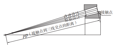
Figure 1 Schematic diagram of original design and improved design
Original design: tapered roller ball base radius SR= ρ p ;
Improved design: radius of tapered roller ball base SR = (0.8 ~ 0.85) ρ p. Among them ρ P is the distance from the contact point between the roller and the inner ring flange to the intersection of the three lines (outer ring raceway, roller centerline and inner ring raceway).
2.2 design of rolling element ball base surface
The radius of roller ball base surface is designed to be 80% ρ p~85% ρ P (the distance from the contact point between the roller and the inner ring retaining edge to the intersection of the three lines), the diameter of the ball base surface becomes smaller, the end face of the roller becomes convex, and the contact area with the inner ring retaining edge becomes smaller.
2.3 crown design of inner ring flange
In the past, the inner ring flange surface of tapered roller bearing was designed into concave arc shape or conical surface shape, and the inner ring flange surface was designed into concave arc shape. When the bearing works, the tapered roller has large contact area, large friction, poor lubrication contact, easy friction and heating, and the limit speed of the bearing is limited; The conical design of the inner ring flange surface reduces the friction and heating, but it is easy to be processed into a concave surface, which affects the service life of the bearing.
The flange surface of the inner ring of tapered roller bearing is designed as a micro convex surface, and the difference between the highest point and the lowest point of the surface is controlled within 0 ~ 2 μ m. Ensure that the roller ball base surface and the large retaining edge surface of the inner ring are in point contact under no load and surface contact under load, eliminate the stress concentration on the contact edge between the tapered roller and the retaining edge of the bearing inner ring, which is easy to form oil film, improve the lubrication effect of the roller ball base surface and the inner ring retaining edge, avoid easy friction and heating, and improve the service life of the tapered roller bearing of the speed increase box.
3. Finite element analysis of antifriction design
This paper uses the finite element software SolidWorks to analyze and calculate the contact between the retaining edge and the roller. SolidWorks is a three-dimensional parametric software integrating computer-aided design, manufacturing and engineering analysis. After completing the three-dimensional modeling of parts in SolidWorks, you can enter the SolidWorks simulation module for analysis. In the finite element analysis module of Solidworks, static analysis, modal analysis, steady-state heat conduction analysis and thermal structure can be carried out.
3.1 create the finite element model
Establish the finite element model according to the structural diagram of the contact form between the inner ring flange and the roller, as shown in Figure 2.
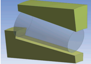
Fig. 2 finite element model
3.2 setting boundary conditions and meshing
In order to ensure the contact form between the inner ring flange and the roller, fix face A in the finite element model and apply load on face B. see Fig. 3 for its constraints and load.

Figure 3 constraints and loads
After the constraints and loads are created, the material properties of the model are defined. Finally, the model is meshed by using the meshing tool provided by SolidWorks simulation. The mesh model is shown in Figure 4.
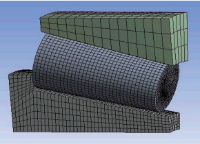
Figure 4 grid model
3.3 analysis results
Through the finite element comparative analysis, the contact between the roller and the inner ring retaining edge is changed from the original line contact to point contact, and the contact area is obviously smaller, as shown in Fig. 5 and Fig. 6.
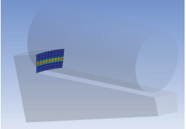
Fig. 5 stress distribution diagram of contact between inner ring flange and roller before improvement of roller ball base surface
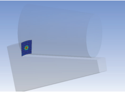
Fig. 6 stress distribution diagram of contact between inner ring flange and roller after improvement of roller ball base surface
4. Test verification of antifriction design
In order to further verify the reliability of antifriction design, the performance test of tapered roller bearing before and after optimization is carried out. First, select two groups of tapered roller bearings that are basically the same except the optimized design part, and test the two groups of bearings respectively to ensure that all test conditions (such as type of testing machine, test speed, test load, load application method, type and amount of lubricating oil, etc.) are the same, and test the bearings respectively under the same test time.
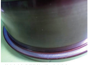
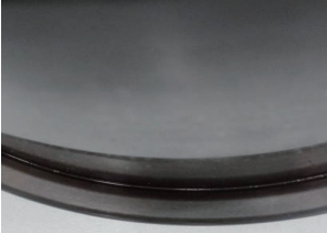
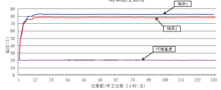
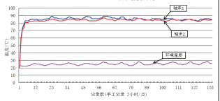
The test results of the two design tests are shown in Fig. 7, FIG. 8 and Fig. 9.
Contact trace after inner ring flange test of original design
|
The bright part of the retaining edge is the contact area, with a width of about 5.3mm |
Improved design of contact trace after inner ring edge test
|
The bright part of the retaining edge is the contact area, with a width of about 4.5mm |
Fig. 7 contact trace of inner ring flange after flange test
It can be seen from the test comparison results that the contact area of the improved bearing inner ring flange and roller ball base surface is smaller than the original, and the temperature is reduced by about 5 ° during the test.
5. Conclusion
Through the finite element analysis and experimental verification of the antifriction design of tapered roller bearing, the improved design can reduce the temperature of the bearing during high-speed operation and reduce the failure probability of the bearing due to excessive temperature change. The design has been widely used in practical production.
Roller contact trace after original design test
|
The bright part of the roller end face is the contact area, with a width of about 5mm |
Improved design roller contact trace after test |
The bright part of the roller end face is the contact area, with a width of about 3.7mm |
Fig. 8 contact trace of retaining edge after roller test
Temperature curve during original design test
|
|
Improve the temperature curve during the design test
|
|
Fig. 9 temperature curve during test
More about WSW Tapered Roller Bearing:
The raceways of the inner and outer rings are tapered sections and the rollers are tapered, so the tapered surface of the raceway and the roller axis (if projected) will intersect at a common point on the bearing spindle. This geometry keeps the motion of the cone coaxial, and there is no sliding between the raceway and the outer diameter of the roller.

This conical geometry produces a linear contact surface that allows greater loads to be carried than spherical (ball) bearings with point contact. The geometry means that the tangent speed of each roller surface is the same as the raceway along the whole length of the contact surface, and there will be no differential scrubbing.

The rollers are stabilized and restrained by the flange on the inner ring, and their big ends slide against the flange, which can prevent the rollers from popping out due to the "pumpkin seed effect" of their conical shape. The larger the half angle of these cones, the greater the axial force that the bearing can bear.
WSW tapered roller bearing adopts outer ring and inner ring assembly. The outer ring is composed of an outer ring, and the cone assembly is composed of an inner ring, a roller and a cage. This bearing structure can withstand combined loads and provide low friction during operation. Rigid bearing applications can be achieved by adjusting a single row tapered roller bearing to a second tapered roller bearing and applying preload.

